
Axonometry refers to an object that is on a single plane where all lines are drawn parallel. The plane offers up a three-dimensional space for the object to be drawn. This particular projection does not have a vanishing point as its purpose is to focus on the dimensions and measurements of an object.
The typical use like orthographical projection, axonometry is used by engineers, construction. architects, manufacturers, and designers. Axonometry was the preferred method of technical explanations. This was a favoured tool to illustrate the designer's thoughts. Technical sketches were used to map out what an object would look like before being built or assembled.
This concept is, in fact, a sub-projection of orthographic projection. Even axonometry has three of its own sub projections.
A brief history on axonometry
Isometrics was introduced by a British chemistry professor William Farish at the University of Cambridge in 1822. In the professor's paper "On Isometrical Perspective" he would explain in detail and produce drawn images of the concept. Although this concept existed centuries before his time, he made the idea of isometrics more widespread.
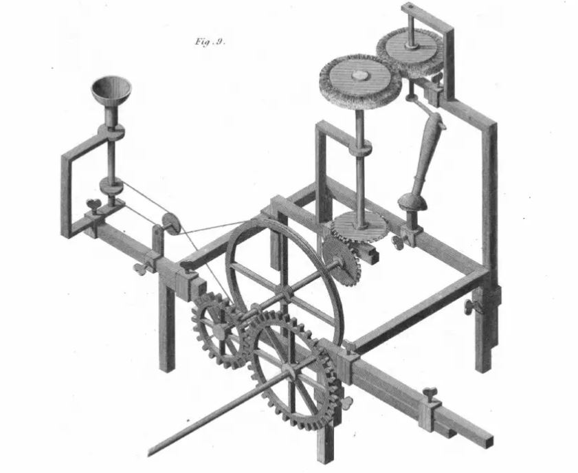
Image source: https://www.scribd.com/doc/193157428/Farish-on-Isometrical-Perspective-1820
In 1962, an American architect and educator, John Quentin Hejduk began a six long year project featuring a series of three technically drawn houses named the "Diamond Configuration". He applied a forty-five degree rotation relative to an orthogonal system to the structures floor plan that gave it a distinctive but analytical approach to his drawings. This approach is said to be simple to construct as it's a vertical projection from a rotated plan.
Moving forward in 2006, author of Quantum Physics and Artificial Intelligence in the 21st Century he goes on to state that isometry is an "invaluable tool for engineers, and soon thereafter axonometry and isometry were incorporated in the curriculum of architectural training courses in Europe and the U.S."
What are the three types of axonometric projection?
There exist three types of projection within axonometry with varying degrees of angles. As it's already a sub projection, this concept has its own subsections as well.
Isometric
The most popular projection of all, the isometric projection. This concept is commonly used by engineers, architechs and graphical designers with strong technical drawing abilities. You have most likely seen this type of projection in infographics on the web or on poster art on your daily commute.
This is where three axes of space are equally distributed with a one-hundred-twenty degree angle shared between them. When drawing up this thirty degree angled projection each dimension has the same scale. Making this one of the easier concepts to work with when coming up with a floor plan or an unusual design in your next project.
Dimetric
Here's where our projections get slightly more complex. We next have a dimetric projection, where the foreshortening along two axes are the same and the third axis is different. For example, two axes can be 116.57 degrees where the third will be 126.87 degrees.
Like above, these are all used in some form of the building plan or technical drawing.
Trimetric
The progressively more difficult projection to work with is the trimetric concept. You can expect that every axis has a completely different foreshortening. This means no equal angles and the axes are typically104.04 degrees, 126.87 degrees, and 129.09 degrees.
Trimetric share the uneven characteristics as another sub projection such as perspective. These two are very unique for their multiple degrees of foreshortening.
What are axonometric drawings used for?
Exploded diagrams
Notable styles in axonometry were "exploded diagrams". These exploded diagrams were illustrated with multiple pieces, evenly spaced out and distributed. Each piece represented a small part of a whole, giving engineers the edge they needed to assemble the object.
You may have seen the exploded design when you were putting together that wardrobe or assembling a shoe rack. Either way, if you are living in the world of technology, there's a high chance of you running into these intricate designs.
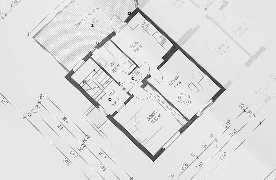
Floor plans
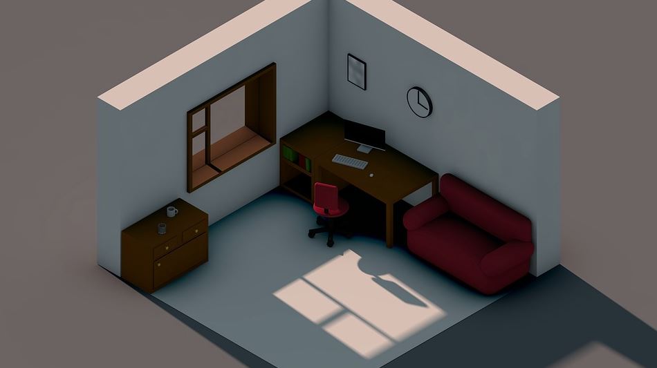
You would find isometrics in floor plans as you would in general building architectural drawings. This is to map out how all rooms, walls, doors, stairs, and windows will be to shape the house's overall design. These plans are accurately drawn ( or 3d rendered ) by technically skilled architects. Two-dimension, three-dimension and live 3d are often used for these plans.
If you are looking to build your home from the ground up, you are going to be working with a lot of isometric drawings.
Isometric graphic design
A popular and rising trend in graphic design is the use of isometrics. Very skilled designers will use this technical method to visually get a specific message across.
Just about anything with a form or structure can be made into an isometric work of art. From simple icons to highly detailed building designs and from billboards to interactive websites, you will begin to notice this style where ever you go. Or, where ever there is technology.