
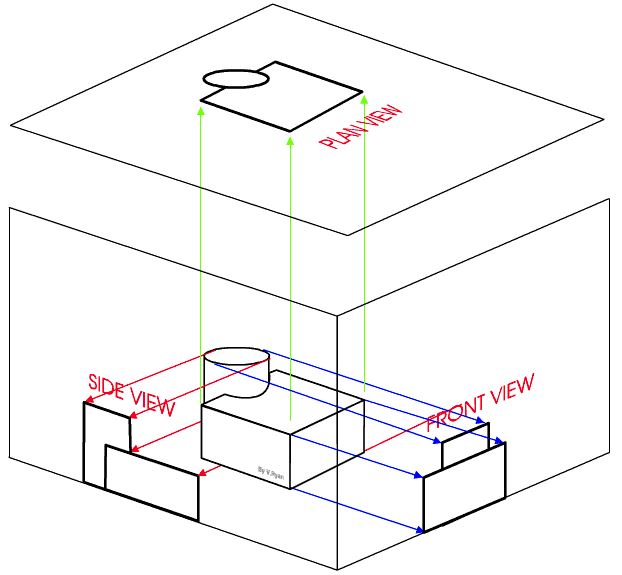
Some times referred to as orthogonal projection, orthographic projection is a three-dimensional object shown in two dimensions. It's a parallel projection where all projection lines are orthogonal to a projection plane. This can be represented by drawing three two dimensional objects merging them into an isometric projection. A front, side and plan view is what's needed to achieve this projection.
Using this method of projection is key in the case of language barriers between clients, designers, builders, and engineers. Those three views are needed to understand how this shape or structure should be built. This method helps clarify where the front is located, the plan and finally the side.
What are the two types of orthographic projections?
This projection works with typically works with drawings using two angles, first angle projections, and third angle projections. The main difference between these two is the positioning of the plan, first and third angles.
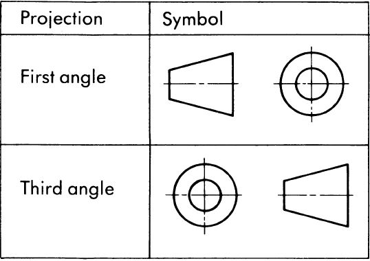
First angle projection
This is done by taking an object's views and placing them on their respective planes. Front view on frontal, top view on horizontal, and side view on profile. When viewing the object is always in the opposite of the viewer and the object is always in the middle in view of the observer.
Third angle projection
The third view forms on their planes, for example, front view forms on the frontal plane, top view forms horizontally and the side forms on the profile plane. The object is always formed to the side of the viewer and the view is in the middle of the object of the viewer.
Keep in mind that they're rules of orthographic drawing. Their rules are recommended to follow whist you form a drawing.
- Front and top form under and over each other
- Front shows a objects length and height
- Side shows the breadth and height
- Top shows length and breadth
- Side forms besides the front
- Projection lines form by meeting two surfaces
- Hidden details of the object is shown by dotted lines
What is orthographic projection used for?
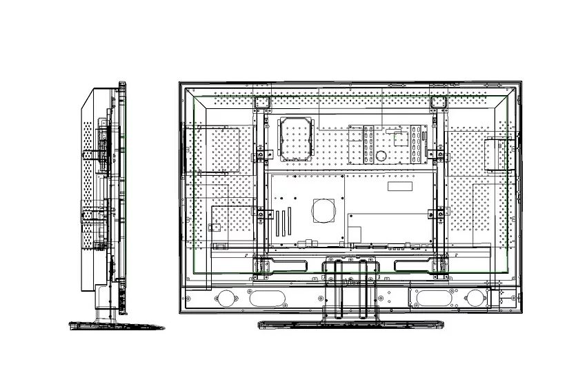
Simply put it's commonly used for anything that requires building. A three-dimensional blueprint of an object on a two-dimensional surface. Other terms can be used such as wireframe to descript an orthographic object. These are plans used for simple objects, to components to larger pieces to an entire functioning object, for example, a motorcycle or a computer monitor.
Engineers, product designers, architects, planners and more use the form of drawing to produce an accurate representation of the final product. The home you live in, the furniture you use, the car you drive and the phone in your pocket were all subjected to having an orthographic plan drawn out for them.
You can even find this method for drawing in furniture assembly. Ever put together a wardrobe with those "detailed" instructions that used an image of what the finished piece resembles? That's orthographic. When they're usually drawn in all separate pieces, it's usually referred to as "exploded diagrams".
What is the difference between orthogrpahic and isometric projections?
The one thing in common that these two projections share is that they both represent an object in a detailed drawing. Basically to ways of showing an object. Also, they're known for being parallel objects.
Isometric
When you see an isometric drawing, you can expect to view an object where the top, side, and front can be seen. This projection's vertical lines are usually drawn on a 30 degree angle horizontally. All of these lines are parallel to the three axis. Isometric designs should have every bit of information displayed in that diagram. If there are shapes behind or holes inside the object, this is where the next projection comes in handy.
Orthographic
This projection also known as a "multiview" diagram can let us see every inch, inside and out of an object. Unlike isometric, we can view what's happening at every angle. Drawing dotted lines are used to show the viewer where and how and holes or hidden parts should be measured.
The real deal is that isometric is a part of orthography's parallel projection.
Types of technical drawing techniques
There are many forms of technical drawings, all have their unique purposes to get the job done. From freehand drawn sketches to detailed computer-generated software, here we'll cover a few examples you'll most likely come across;
Drawing instuments
This is the classic method of getting your technical information visualized on paper. These can make for a quick sketch upon a simple project you are building. The typical toolset used of this technique includes fine pencils and pens, compasses, rulers, square, scales, templates, and stencils.
Freehand
For probably more skilled artists, this requires a seriously steady hand for getting those straight lines. Typically they will use a pen, pencil and some grid paper.
3D and computer generated
To go even further, this technical drawing has been around as long as the others, minus the computers. 3D technical drawings are three-dimensional objects represented on a two-dimensional space. All of the above tools are used for this technique to achieve the design. When it comes to computers, you can create an even further refined and accurate depiction of your object. 3D CAD software is typically used for this.
Whatever technique you choose, each one will fall under using the use of orthographic projection.